Robo-Dog Roll Cage
As a member of the Design Automation of Intelligent Systems research lab at Northwestern, I was tasked with creating a mounting solution for a Unitree Go 1 robotic dog. It should provide a mount for a Nvidia Jetson Orin Nano while also protecting from rolling conditions. Here is what I came up with…
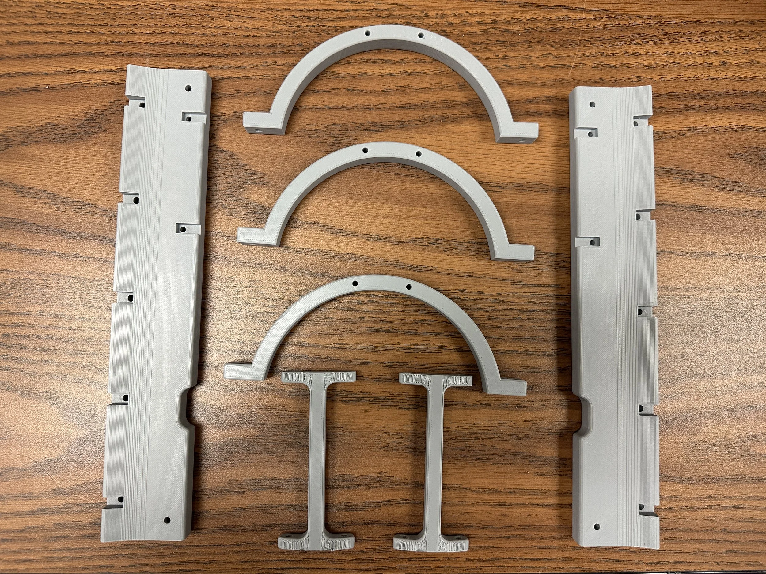
The Parts…
The Assembly
FEA Analysis
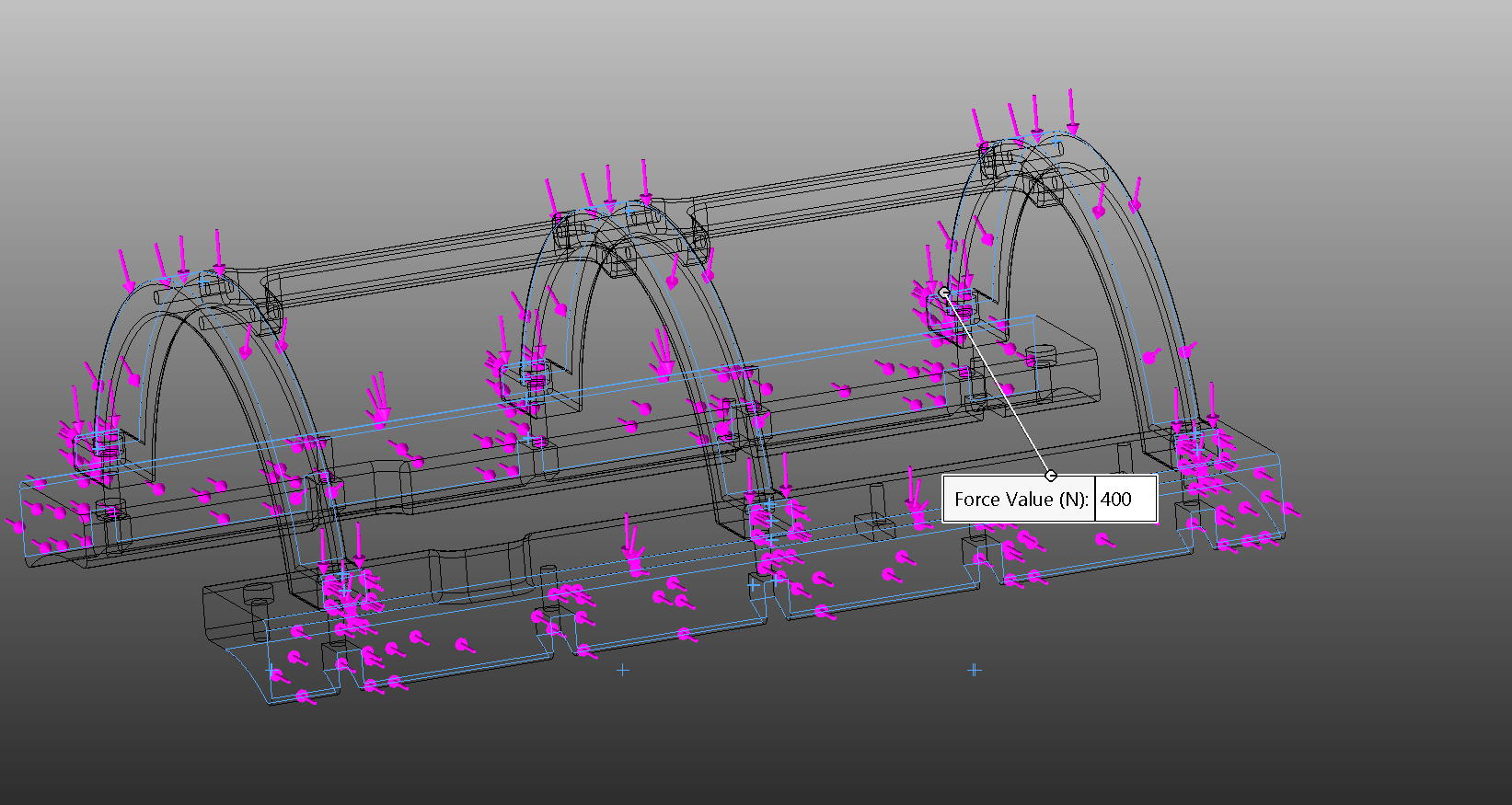
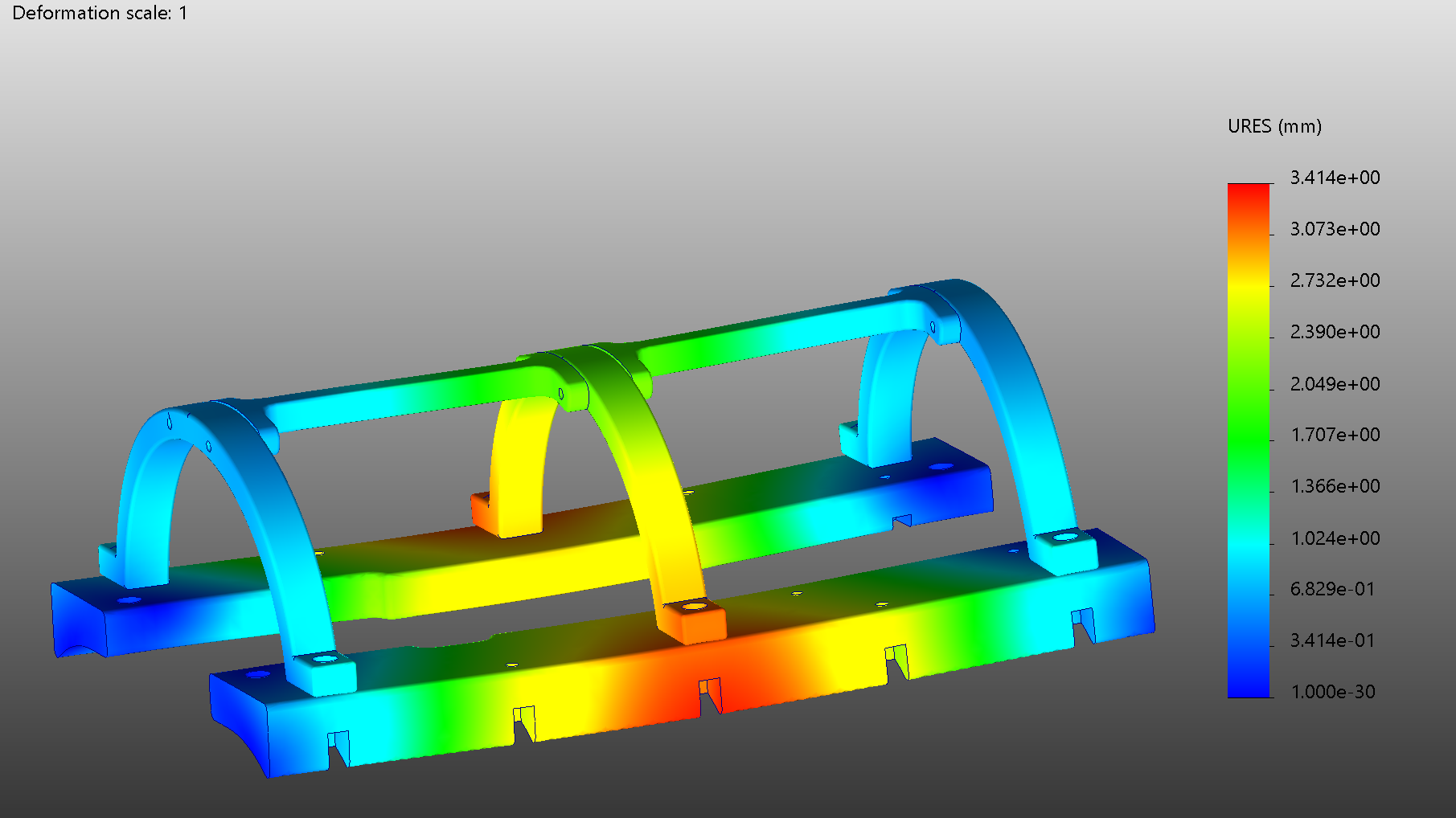
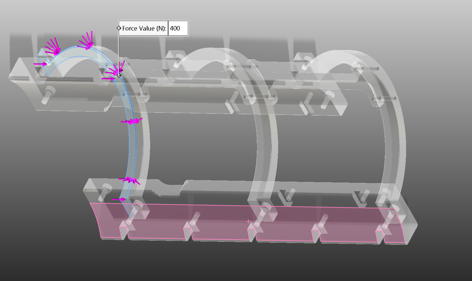
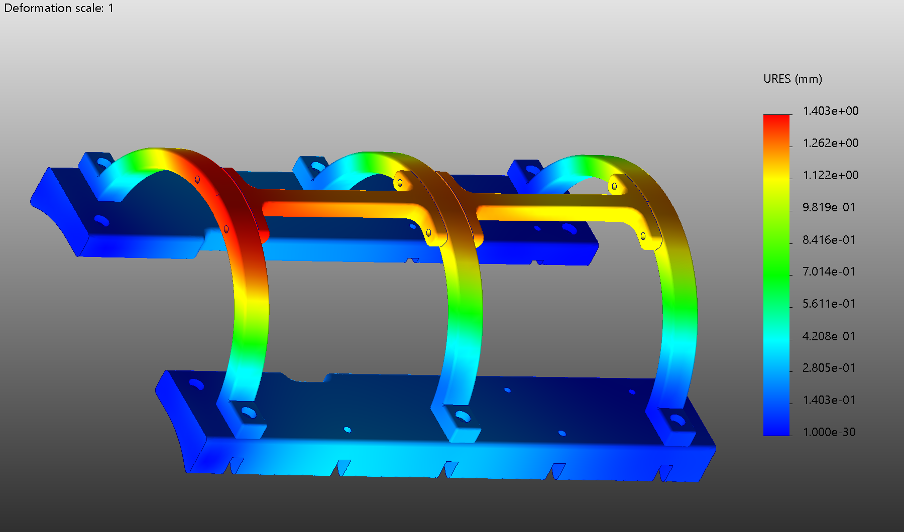
In conducting the Finite Element Analysis (FEA) for a mounting bracket and roll cage, I selected ABS as the material for all components due to its compatibility with 3D printing, facilitating an accurate representation of the final design during the prototyping phase. The primary goal of the FEA was to validate that the design would effectively shield an Nvidia Jetson from damage in rolling conditions, necessary when testing cutting-edge AI algorithms. The initial prototyping was conducted using PLA, providing a cost-effective and timely means to refine the model's geometry. Subsequently, the final version will be fabricated from nylon reinforced with carbon fiber, significantly elevating strength and durability. The applied force for the FEA was set at 400N, a conservative figure that is over three times the baseline force of 120N calculated from the anticipated operational weight of the bracket and cage. This rigorous approach not only assures structural integrity under high-stress scenarios but also underlines my commitment to developing robust and reliable protective systems for high-value electronic components in dynamic environments.
Horizontal Loading Application
Deformation
Forward Rolling Application
Deformation
Preliminary FDM Prints
The initial prototypes were successfully printed, exhibiting precise alignment with the major geometrical specifications. During assembly, the cage seamlessly integrated into the pre-designed screw mounts, affirming the accuracy of the initial design. Notably, we optimized the assembly by replacing M2.5 fasteners with M3s, considering their higher availability at the lengths necessary. The forthcoming phase involves fabricating the final design using carbon fiber-reinforced nylon, aiming for enhanced durability and performance.
Final Product
Coming soon…
Up Next:
Use bolted connections in FEA analysis instead of bonded contact surfaces
Make any changes and print out the final product in nylon with carbon fiber reinforcements
Last updated 1/22/2023
